
 DE
DE ES
ESWhat Happens at Compacting of Concrete?
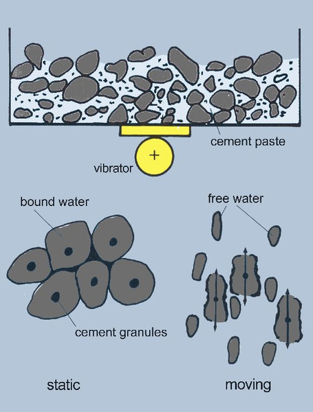
- Fig. 17: Surplus water activation at vibration
The uncompacted fresh concrete consists of cement, surcharges of different grain size (sand, split, gravel), and water. Through mixing the necessary uniformity of the compound is ensured. The concrete which is filled out of the mixing unit to the shuttering, because of the many air bubbles has much air pore space, which is equivalent with low concrete strength. Therefore the air has to be brought out of the concrete again.
Vibration effects that the cohesion and the friction of the concrete constituents are strongly decreased. Thus the density of the grain particles increases and the trapped air is pressed to the surface and escapes. The coarse grain of the concrete should only move little to avoid demixing. The coarse grain should only be moved so much that the edges of the grain bodies align to each other; so that thus the remaining interspaces become as small as possible and a high density is reached. The through the vibration created surplus water of the fresh concrete promotes this process (reduced friction) and fills up the remaining spaces between the coarse grain particles. The surplus water is activated by tearing open the surface tension of the water drops which surround the cement grains. For this process high acceleration and high vibration frequencies (100-200Hz) are necessary.
At compaction of concrete, mainly at large-scale moulds and shutterings, predominantly high frequency external vibrators 6000 rmp and seldom vibrators with 12000 rmp are used.
|
Advantages of High Frequency External Vibrators Surplus water gathering at fresh concrete is intensified by High Frequency External Vibrators
Low movement of coarse grain particles because of a small vibration amplitude
Small vibration amplitude at increased frequency
Small resonance vibration and small increase of the amplitude Large, not vibration rigid shuttering and forms can even be vibrated zonally → light weighted forms Excellent penetration of vibration through insulation layers (e.g. at sandwich elements). Perfect surfaces through evenly distributed vibration transmission. High frequency external vibrators have high electrical power reserves, which also at great changing load ensure the highest degree of centrifugal force and rotation constancy. |
External Vibrators with 6.000 Rotations/Minute
At 6.000 vibrations/min at on side the vibration amplitude is small enough to avoid demixing, on the other side it is big enough to distribute the vibration at the mould so much, that the external vibrators don’t have to be attached too near to each other. Less external vibrators are needed to compact the same area evenly as at use of external vibrators with higher vibration speed. Furthermore the velocity, with which the compacting progresses out of the vibration centres, is higher, i.e. the vibration period is shorter.
It is important, that at equal damping by the concrete due to the bigger vibration amplitude a better depth effect is achieved and thus thick parts get high density. Even more important as at massive elements is this at so-called sandwich elements since the vibration has to penetrate the insulation layers.
External Vibrators with 12.000 Rotations per Minute
External vibrators with 12.000 vibrations /min theoretically allow a more intensive compaction than those with 6.000 rpm but, because of the very small vibration amplitude, can only be used, when the forms are so rigid that they transmit the vibration amplitude without any loss.
Moreover the effective range is relative small and the noise development very big. External vibrators with 12.000 rpm mostly are used at the production of parts which demand the highest degree of stability and density, i.e. at concrete pipes.
The vibration capability and resonance behaviour of a shuttering are not possible to be determined beforehand since the influences of the construction, material, mounting, connection elements, vibration transmission, kind and composition of the concrete are difficult to grasp.Therefore at determining of the centrifugal force empirical values are used. In practice the following formula is proven:
Fc = m ⋅ a ⋅ S / 1000
Fc - centrifugal force kN
m - here: mass of the vibrating parts of the vibration equipment + mass of the vibrator + 10% of the mass of concrete in kg
a - acceleration in m/s2 (see Tab.4)
S - characteristic value for rigidity and the resonance behaviour of the vibration equipment (see Tab.5)
|
speed n (v/min) |
mechanical frequency fm (Hz) |
acceleration a (m/s2) |
Vibration amplitude s (mm) |
|
3000 |
50 |
30 - 50 |
0,60 - 1,00 |
|
6000 |
100 |
60 - 80 |
0,30 - 0,40 |
|
12000 |
200 |
100 - 120 |
0,12 - 0,15 |
The resonance behaviour and more or less vibration inclination of shutterings normally lead to excessive change of the vibration amplitude and therefore the acceleration a. In order to keep the approximate values for a, a is reduced with help of the characteristic value S (see Fig.18).
|
Experience values for the characteristic value S | |
|
Battery mould elements |
S= 0,1 -0,12 |
|
Big vibration tables |
S= 0,14-0,18 |
|
Palettes on vibration trestles |
S= 0,16-0,2 |
|
Rigid special-forms |
S= 0,2 -0,5 |

- Fig. 18: Reference values for acceleration a and determination
of corrected values (a x S) at given vibration speed n
The concrete mass is proportionated only with 10% of its mass in the calculation because the fresh concrete as one mass at uncompacted state is not considered as part of the mass, which has to be brought to vibration. At the proceeding compacting process this changes slowly. Not until the end of the vibration period, the better part of the concrete has to be considered as vibrating mass. This is also seen at the decrease of current consumption of the external vibrators during the proceeding compacting period.

- Fig. 19: a/s diagram. The hatched area shows the beneficial scope. Above this area, at low vibration speed, s gets too big, and at high vibration speed, a gets too big. Below the hatched area, at low vibration rates, a gets too small, and at high vibration speed, s gets too small
An example makes the interconnections clear:
|
Given: |
A vibration table with dimensions 10m x 4m, mass of the table and edge formwork 6350kg, mass of the external vibrators 225kg, mass of to compacting concrete 18000kg. It has to be compacted with 6000 vibrations/minute. |
|
Searched: |
Centrifugal force Fc |
|
Answer: |
a = 80 (see Tab.4 and Fig.18) |
Fc = [(6350 + 225 + 0,1 ⋅ 18000) ⋅ 80 ⋅ 0,15] / 1000 kN
This total centrifugal force is divided to several vibrators; at a total of 9 vibrators every vibrator has to generate 12kN (reference values) centrifugal force.
The particular vibration period depends on several parameters, viz. the magnitude of acceleration, the demanded strength, the vibrating mass, the composition of the concrete, the height of the concrete in the form, and the arrangement of the armor. The vibration period is sufficient when the surface is closed by fine mortar, only few air bubbles ascent of the concrete, and it - in case of hard concrete - deforms only at strong pressure of the hand during the vibration period. Sporadic, discontiguous air bubbles at the surface and in the concrete usually at compaction cannot be avoided. They don’t have any influence on the mechanical properties of the hardened concrete.
|
at n [l/min] |
12000 |
6000 |
3000 |
|
a [m/s2] |
120 |
80 |
50 |
|
s [m/m] |
0,15 |
0,4 |
1,0 |
|
results at: | |||
|
Coarse grains: |
almost no motion,no support for alignment |
small motion, support for alignment |
large motion, risk of demixing |
|
Cement paste: |
very much surplus water |
much surplus water |
somewhat surplus water |
|
Effective range: |
weak |
medium |
strong |
Shutterings and Forms
At precast concrete plants for production of large-sized concrete elements these different forms and shutterings are used:
- vibration tables
- lanes for ceiling elements
- palettes for vibration stand stations
- column and beam forms
- double-T forms
- battery formwork and vibration beams for sandwich walls
- garage forms
- box culverts
- large tube forms
- stair forms, amongst others
Vibration Tables
There are two forms of vibration tables: the tilting table and the oscillating tilting table. The tilting table is a rigid, warp resistant table with a very small flex tolerance, which can be tilted (hydraulically) for the removal of the precast element. With an oscillating tilting table the upper construction is separated from the lower construction and mounted on isolators. The mass to be set into vibration is less, so that working with smaller external vibrators is possible but the flex tolerances on only partially poured tables are larger.
For the installation of the external vibrators on vibration tables, the shifted W-arrangement of vibrators on the main longitudinal beams is the best proven in method. It is important to adequately stiffen the mounting location of the high frequency external vibrators.This assembly is used because each external vibrator only vibrates its’ surrounding area and these areas barely overlap.On oscillation tables, the external vibrators on vibration plates are attached parallel to the longitudinal beams. Again, the shifted W-arrangement best ensures an even distribution of vibration to the whole table.
As another example, the group of rod-shaped forms is considered: column and beam moulds as well as double-T forms.

- Fig. 20: Established arrangement of external vibrators at tilting- and oscillating tilting tables.
|
Table dimensions |
Number of vibrators |
|
3,0 x 6,0 m 3,5 x 8,5 m 4,0 x 10,0 m 5,0 x 15,0 m |
5 5-7 9-11 11-15 |
Column and Beam Moulds
Column and beam forms are available, as individual or double form, with variable side and bottom moulds in lengths of up to 60m. Whether producing pre-stressed or standard precast products, intense compaction is needed in the re-enforced areas. It is necessary to attach I-Beams horizontally at different heights on which the high frequency vibrators are to be attached. This ensures optimum compaction. In the case of double beam moulds, an additional HF external vibrator is attached under the core.
Double-T Forms
Double-T forms are used mostly to produce ceiling elements. This form can also be 60m and longer. These forms can be hydraulically or mechanically equipped. The height of the ‘T’, width of ‘T’, distance between the ‘T’s and width of slab can be changed. I-Beams are mounted to both sides of the ‘T’ in order to attach the high frequency vibrators.
Because of the adjustability of these forms, variable frequency converters provide the needed flexibility. (vario-frequency converters).

- Fig. 21: Arrangement of external vibrators at double-T forms

- Fig. 22: Arrangement of external vibrators at column forms
Other Applications
In addition to the concrete compaction on large-scale forms, high frequency and standard frequency external vibrators are used in other various applications:
- block forming machine (main- and top vibration)
- slip former (vibration bridge)
- hollow-core slab former (vibrating screed)
- tube forming machine
- small forms (manholes, sewers, wells)
- single tube forms
- manufacturing of concrete railroad ties
Frequency Converters
At high frequency external vibrators the mains frequency (50Hz) has to be increased with frequency converters to 200 Hz (output frequency f2) There are also vario-frequency converters which generate a variable output frequency f2 This means also, that the vibration speed (rotation) of the vibrator is variable.
n = 60 ⋅ fel / p
A change of the motor speed causes a change at centrifugal force:
Fc2 = Fcl ⋅ (n2 / n1)2
With vario-converts the centrifugal force of the vibrator can then be changed during operation. This has the advantage that the centrifugal force can quickly be adapted to the respective fill factor of the formwork and to the compaction state of the concrete.(In practice the range between 80-210 Hz as working frequency is proved as useful.)
The three-phase asynchronous motor of the external vibrator at this frequency change works always at the optimal working range since the frequency and voltage always are changed at the same ratio (U/f = constant).
Advantages of Variable Frequency
Since the vibration width is independent of the rotation speed, at frequency adjustments always is worked with same vibration width (amplitude) but changing acceleration (see relationships).
Since the height of the sound pressure level produced by the external vibrator is really influenced by the frequency and acceleration, which have an effect on the shutterings, with a proper application a noise reduction of up to 15 dB(A) can be realized. A substantial effect of the frequency change is that at an optimum compacting force as little noise as possible is generated. For example, concrete is filled in layers when concreting rod-shaped forms (beams, stanchions, girders). If the vibrators already work at maximum power when the form is still almost empty (this is the case with fixed output frequency), a large part of the energy produced is lost in the vibration of the empty form (the upper part), which also produces unnecessary noise.Because excessive centrifugal force also causes fatigue of welded seams and shaking loose of parts (e.g. heating pipes), there will be less wear and tear on the vibrator equipment when the centrifugal force is properly adjusted.

Fig. 28: electronic vario-frequency converters in a control box

Fig. 29: electro-mechanical vario-frequency converters with built-on special control box
Shutterings and large-scale forms are complex structures; often several natural vibration figures occur which in advance hardly can be determined. Is this natural vibration near the usual fixed frequency, large local resonance can occur, which in turn, because of the heightened acceleration amplitude, creates a higher sound pressure level. The resonance vibrations are very harmful for the form.
A great opportunity to use the benefits of vario-converters to its full capacity is the control of the facility per remote control. At this case the operator controls the facility direct at the form and influences the compaction process according to the status of procedure. Depending on the part and composition of the concrete, it is then possible to individualize the compacting process. Accordingly good results are achieved.
Types of Vario-Frequency Converters
The Vario-converter can be a rotating (electro-mechanical) or a static frequency converter (electronic). The decisive advantage of mechanically adjustable frequency converter is that an external vibrator and even entire vibrator groups can be connected to the running converter. That is possible because it copes easily with overloads and current peaks. Therefore it qualifies also as a central converter in companies, in which various production facilities are operated.
The electronic frequency converter, on the other hand, suites as supply for a production unit, e.g. vibration equipment, a double T shuttering or column forms, i.e. the number of external vibrators per group, which run simultaneously, has to be fix. ››Hooking up‹‹ of a second vibrator group can only be carried out with a second frequency converter or after stop and new start of the first group. This is due to the high currents of starting vibrator groups, which in normal case exceed the permitted overload-current of the running converter. Therefore the operating procedure and the method of operation have to be determined exactly in advance. In no case professional advice should be omitted. At automating of production sequences vario-converters can be combined with programmable logic controllers. This coaction is used e.g. to save (on PC or on PLC) and reproduce the parameters of compaction (vibration period, frequency, part number, number of the vibration equipment, etc.), which have brought to good outcome, as often as required.
Electrical Installation
High frequency vibration equipment consists of external vibrators, central frequency converter, control and distribution cabinet as well as radio controls.
Since each installation has to be adapted to the operating procedure, general guidelines are not applicable. But it is important, that the external vibrator is always equipped with a vibration-proof power cable, a motor protection switch provides the protection of the vibrator and formwork, and the vibration equipment is installed properly, i.e. properly installed cable, converter, control- and distribution cabinet.
High frequency external vibrators are available for operating voltages of 250 V and 42 V. For new installations, the 250-V installation system has asserted itself with installations, since smaller cable cross sections and inexpensive switching elements can be used here. At the 250-V installation system the electrical safety is ensured by the required protective conductor which makes the application of the following protective measures according to VDE 0100 possible:
- protective grounding (§9N)
- connection to neutral (§10N)
- protective conductor system (§11N)
- ground fault circuit interrupter (§13N)
Noise Reduction
For the evaluation of the noise not only the height of the produced noise level at a moment but also its working time is decisive. The permitted noise level at new installations of vibration equipments lies at 85 db (A) over 8 hour/day. This is equivalent to e.g. 97 dB (A) over 30 min/day.
There are several possibilities to reduce the noise level, which is produced by the installation facility for concrete compaction:
- enclosing and covering of the vibration device
- noise reduction directly at the forms
- application of dampening materials
- noise reduction construction
- use of adjustable frequency converters
Enclosing and Covering of the Vibration Device
The possibility to enclose certain production areas to reduce noise makes only sense at flow-production like vibration stations or similar machines. At production in large-scale shutterings this type of noise reduction is not possible.
Noise Reduction at the Form
The shuttering must be kept free by loose and clattering parts. That means in detail: No tools or other small parts may lie on the shuttering. No loose bolts or screws, no loose heating pipes or other loose construction parts may be at the shuttering.

- Fig. 30: Causes of noise generation during vibrating
Application of Dampening Materials
With usual dampening materials a radiation of sound at large-scale shutterings and/or their thick-walled sheets and beams can not be prevented.
››Panelling‹‹ of vibration tables with dampening mats of high specific weight has little effect. Noise reduction up to 10 db (A) brings a for this application special developed method for primary sound absorption, the ››Baryvibo system‹‹. It is a three-layered sandwich system with a viscoelastic interlayer of synthetic resin at which available metal constructions (profiles, sheets, and beams) are included as reinforcers to the system. The Baryvibo system dampens arising free bending vibration at beams and sheets which cause only noise and are not necessary for the compaction. The function of the vibration facilities still is ensured.
Noise Reduction Construction
Already at the construction of new vibration facilities the development of the noise can be taken into account and thus kept as low as possible. It must be taken into account that the shuttering is dimensioned sufficiently both in static and dynamic regard. Thus for example by sufficient, evenly distributed stiffening, resonances can be prevented.
Special attention also has to be given to the welded joints. The form surface and lower con-struction must be force and form-fitted connected with each other and mustn't beat on each other (welding steps too big).
Application of vario-frequency converters
In addition, as mentioned, adjustable vario-frequency converters also contribute to the reduc-tion of the noise since at optimal compaction unnecessary noise is prevented. Particularly mechanical adjustable vario-converters are recommended.